Precision instruments, metrology, fluorescence, low-noise analog electronics – that’s what we do.

Infrared CO2 Measurement
These notes describe the opto-mechanical engineering I contributed to a Pellistor that can detect elevated levels of CO2 in the air.

Cornea Glare Test Instrument For MEEI
This custom built instrument will allow Dr. Rony Sayegh at the MEEI (Mass Eye and Ear Infirmary, Boston, MA) to improve the sight of his patients.
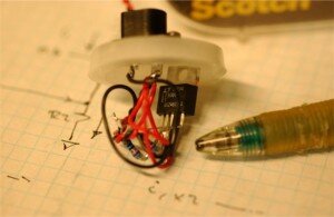
LED Current Source Based on LT3080, The Modern LM317 Replacement Part, Runs Off USB or 9V or Any Voltage in Between
This 20mA current source will operate from a USB 5V power supply.

Blue LEDs Make Healthy Babies – Firefly Phototherapy From Design That Matters
At an early stage in this project, Pete provided measurements and guidance about the most effective LED optics for the jaundice cure for new born babies.

Eye Exam Using a Smart Phone, And Some Plastic Optics – The NETRA Project
Pete has been working with some folks at the MIT Media Lab, in particular the Camera Culture Group of Ramesh Raskar.
Energy Harvesting – Battery-Free Radio
We’re working on some energy harvesting projects – and we learned about this amazing project – a radio powered only by the sound of the voice of the person talking at the transmit end.

High Voltage Testing of 208VAC Phase Controller Used On Semiconductor Production Equipment
This phase controller uses the tried and true back to back SCR technique.

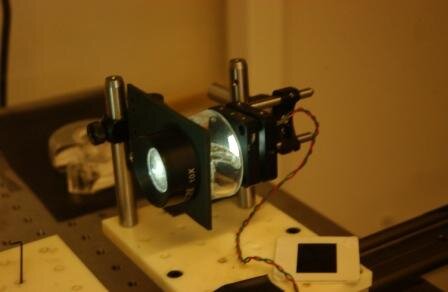
Photos of Recent Work
Here’s a photo of an LED light source and image projector under test

In The Future, Robots Will Have Arms
The kind of arms to pick up things, not like the puny arms that a T-Rex has.

Arduino Motor Control
We’re using some Arduino boards for a variety of projects – to run the motion stage (25um resolution), to test LED colors, to run an oven for testing temperature compensation electronics.